Vetra Blazer Assembly Guide & VideoUpdated 4 months ago
Watch and wrench along with our included step-by-step assembly video.
Vetra Blazer Assembly Guide Introduction
This Vetra Blazer assembly guide walks you through assembling and setting up your brand new Vetra Blazer from the shipping crate to dirt-ready. It follows the same order shown in our Vetra Blazer Box-to-Dirt assembly video: uncrating, bars and controls, wheels and shock hardware, battery removal/charge/reinstall, cable connections, number plate, foot pegs, and first-time display settings.
What’s Included with Your Vetra Blazer
- Vetra branded charger
- ODI-style number plate
- Zip ties for number plate (4)
- Rubber cable ties for cable management (4)
- Left + right foot pegs
- Peg pins
- Peg springs
- Foot peg cotter pins
- Front fender hardware
Tools & Supplies Needed
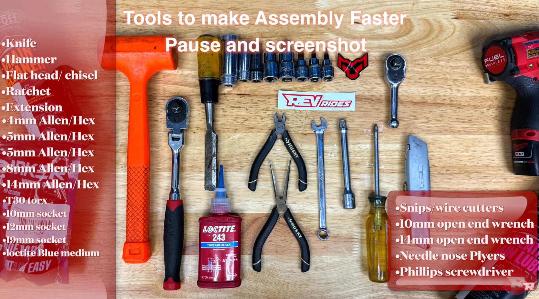
Tools
- 12mm socket + ratchet (impact optional)
- 10mm wrench (left side rear shock hardware)
- 12mm socket (right side rear shock hardware)
- 8mm hex key / hex socket
- 5mm hex key (fork pinch bolts)
- 4mm hex key (controls, stem clamp, fender bolts, bar clamp check)
- 14mm hex socket (hold axle side while tightening opposite side)
- Side cutters / flush cutters (zip ties)
- Needle-nose pliers (cotter pins)
- Flat screwdriver (peg spring + cotter pin spread)
Supplies
- Medium-strength blue Loctite (never red)
- Grease (axle, rear shock pivot bolt, optional on peg pins)
- Rubber/plastic drift + dead blow mallet (if axle needs persuasion)
- Small wood block (to lift/support rear wheel on a stand)
Before You Start
- Wear eye protection and cut-resistant gloves. Crate hardware can be sharp and packaging may splinter.
- Do not discard packaging until you’ve confirmed the bike is undamaged and fully operational.
- Please notify REV Rides within 48 hours of delivery if your bike is damaged or not working upon arrival.
- Cut zip ties carefully. Do not cut wires, brake lines, or connectors.
- Keep the rear brake master cylinder upright any time the brake lever/brake assembly is loose.
- Always start threading bolts by hand. Hardware can cross-thread or snap if rushed or power tools are used.
- A second person is recommended to assist in lifting the bike out of the crate safely.
Step-by-Step Assembly Instructions
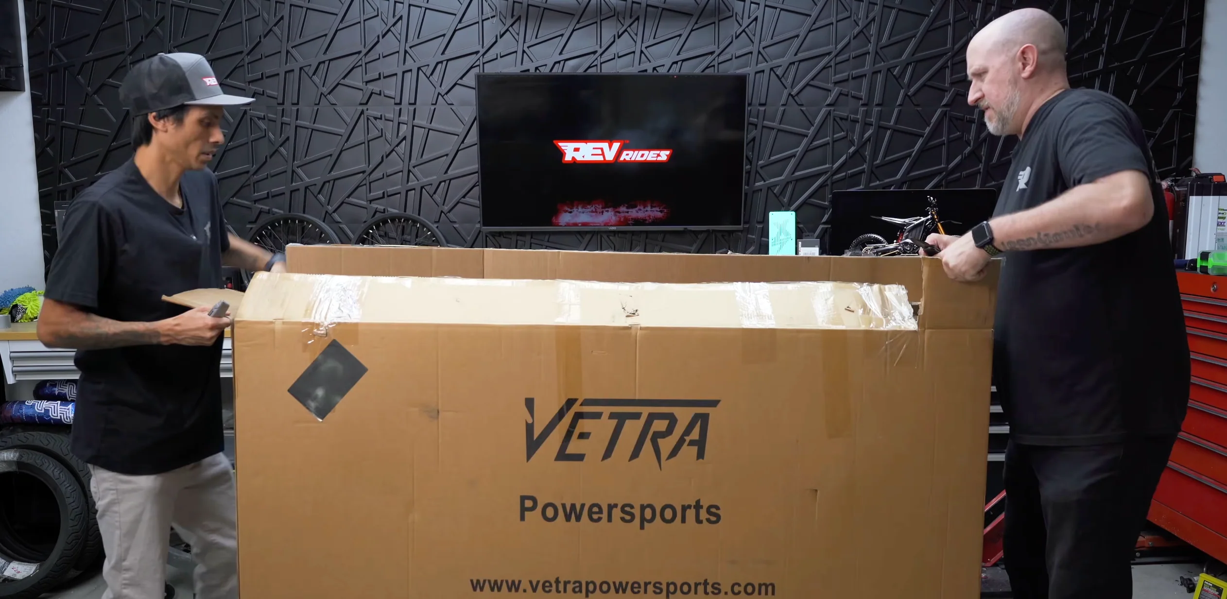
1) Uncrate the Bike
- Remove the crate fasteners.
Tool: 12mm socket/ratchet (impact optional) - Remove loose components and set aside.
Tip: Don’t scratch the front fender while sliding parts out. - Cut zip ties holding the handlebars and let the bars hang to the side for now.
Warning: Don’t cut any wires. - Lift the bike out of the crate.
Tip: Use a buddy.
2) Position the Handlebars (Temporary)
- Place the handlebars in position and snug the clamp lightly.
Tool: 4mm hex (as referenced for clamp tightening) - Confirm brake lines and cables are routed cleanly.
- Nothing snagged
- Nothing binding
- Bars can turn without pulling anything tight
- Center the bars roughly. You’ll position and fine-tune later.
3) Install and Position the Rear Brake Lever & Controls
- Cut the zip tie holding the rear brake lever assembly (the lever may flick outward when released).
- Keep the master cylinder upright the entire time.
- Loosen/remove the clamp bolts and place the lever assembly on the bar.
Tool: 4mm hex - Start bolts by hand. Tighten evenly.
Warning: These bolts are easy to snap. Avoid power tools for starting. - Leave final angle adjustments for later.
4) Remove Shipping Safety Straps
- Remove the safety straps from both sides.
- Keep them (you may want them later).
5) Front Wheel Installation (Axle, Spacers, Pinch Bolts)
- Remove the yellow brake spacer when ready.
- Identify your spacers.
Larger spacer = rotor side. Video callout: small spacer on the right, large spacer on the left (rotor side). - Lightly grease the axle.
Tip: Gloves recommended. - Install spacers into the hub.
- Pivot one fork leg slightly to make alignment easier, then guide the wheel into place.
- Slide the axle through and align both fork legs.
- Start axle threads by hand.
Tools: hold one side with 14mm hex socket, tighten other side with 8mm hex.
Tip: Hand tight only. Pinch bolts do the real clamping. - Check pinch bolts for factory Loctite. If missing, apply medium blue Loctite (never red).
- Tighten pinch bolts evenly.
Tool: 5mm hex. Alternate sides once you feel resistance.
6) Rear Shock Hardware
- If using a stand, lift the rear tire slightly and slide a wood block under it for leverage.
- Loosen shock hardware.
Tools: 10mm wrench (left), 12mm socket (right) - Add a small amount of grease to the pivot section of the bolt.
- Tap shock into alignment if needed, slide the bolt through, install the locking nut.
- Snug down: hold the 10mm side, tighten the 12mm side.
7) Battery Removal & Charging
- Remove seat fastener and lift seat off.
- Turn key to the right and open battery lid.
- Unplug battery (twist to the right, pull out).
- Remove battery hold-down brackets.
Tool: 10mm - Lift battery out using the two straps.
- Charge port clarification:
- The side port charges the battery.
- The top port is for the comm sport connection in the bike (per video).
- Plug charger into battery:
- Align: half moon on top, triangle on bottom
- Twist to lock
- Charger LED: blue = charging, green = full
8) Front Fender Install
- Apply medium blue Loctite to each bolt.
- Start with the rear bolt first to make alignment easier.
Tool: 4mm hex - Install remaining bolts and snug evenly.
9) Connect Cables & Zip Tie Management
- Remove keys from the front area and store temporarily so they don’t snag.
- Connect cables by aligning the notch/extrusion or arrows, then gently twist to seat.
- Route neatly (video routed green line behind brake line).
- Before tightening anything down:
- Turn bars full left and full right
- Confirm nothing binds or pulls tight
- Add zip ties near the white plugs to prevent pull-through:
- Snug, not crushing
- Cut tails carefully (don’t nick wires)
10) Number Plate Install
- Feed zip ties into the number plate first.
- Start with two corners to center it, then add the other two.
- Route behind brake lines on the brake side.
- Tighten once aligned, then cut tails.
11) Foot Peg Install
- Optional: grease peg pins lightly to reduce noise.
- Position peg and spring.
- Use a screwdriver to hold spring while pushing pin through.
- Install cotter pin through the hole at the end of the peg pin.
- Split cotter pin ends with screwdriver, then bend each end outward using needle-nose.
- Repeat on the other side.
12) Rubber Cable Ties (Cable Management)
- Install rubber cable ties in the key wire locations shown (upper run, mid run, near controls).
- Rotate ties so they’re less visible if desired.
- Expect tighter fit near bends. That’s normal.
13) Reinstall Battery + Brackets + Seat
- Reinstall the battery. Ensure it’s fully seated and aligned.
- Install battery brackets.
If brackets fight you: the battery is misaligned. Do not bend brackets.
Tool: 10mm to tighten - Reconnect the comm cable (should drop in if aligned).
- Close battery lid. Don’t force it.
- Reinstall seat: align the notches correctly.
If misaligned, the seat bolt will fight you. - Snug seat bolt (don’t over-tighten).
Tip: slight forward pressure helps threads start.
14) Final Bar Alignment & Stem Tightening
- Loosen stem clamp bolts slightly, straighten bars precisely.
Tool: 4mm hex - Tighten stem bolt to pull the front end together.
Tool: 8mm hex - Tighten stem clamp bolts evenly left/right.
- Double-check the 4 handlebar clamp bolts on top are snug.
Tool: 4mm hex - Adjust display angle, brake levers, re-aim headlight, then snug everything.
First Power-On & Important Display Settings
Power On
- Hold M until the passcode option appears.
- Tap the NFC key (red or black) to the NFC pad to fully turn on.
Recommended First-Time Settings
- Enter menu: hold Up + Down
- Change km/h to mph
- Set battery indicator to percent
- Adjust brightness to preference
Password (Optional)
- Enable boot password if you want the bike to require a passcode at startup.
- Set your password in the password menu (video example used 000000).
Final Assembly Checklist (Before You Ride)
- Bars straight, stem bolt tight, stem clamp bolts even
- Bar clamp bolts checked and snug
- Axle started by hand and seated correctly
- Pinch bolts evenly tightened (blue Loctite present)
- Front wheel spins freely, brake functions normally
- Rear shock hardware snug and secure
- Foot pegs pinned correctly, cotter pins bent and locked
- Fender bolts installed with blue Loctite and snug
- Cables fully seated, routed cleanly, no binding at full lock
- Battery seated, brackets installed without force, lid closes normally
- Seat seated in channels, seat bolt snug
- Display set to MPH and battery percentage
- Review the pre-ride checklist before your first and every ride: Pre-ride safety checklist for e-motos & mini-bikes
Common Mistakes to Avoid
- Cutting a zip tie and nicking a wire or brake line
- Letting the rear brake master cylinder flip upside down while mounting the lever
- Cross-threading small clamp bolts by using power tools too early
- Forcing battery brackets (misaligned battery is the real issue)
- Tightening axle too much before pinch bolts are evenly clamped
- Over-tightening fasteners that are easy to snap
- Discarding packaging before confirming the bike is undamaged and fully operational